
Industries & Impact
From 3D Scan to Cast Part: What Your Scan File Actually Needs
If you already have a 3D scan of the part and want a real short-run casting quote back, a usable scan file needs five things: (1) a watertight mesh in STL, PLY, or OBJ (or a parametric solid in STEP / IGES), (2) mesh resolution fine enough on the critical features that triangle edges sit at or below one-third of the tolerance, (3) recovered wall thickness anchored to unworn reference geometry, (4) a stated coordinate system, up-direction, and units, and (5) either the alloy call-out or a coupon so we can identify it. Get those right and the scan drops straight into a patternless 3D-printed sand mold — typically 3–5 weeks to a poured, machined, inspected replacement, no minimum, no tooling, USA-made.
Who this is for
This page is written for the procurement engineer, design engineer, or reliability engineer who has (or is about to have) a 3D scan of a broken, worn, or obsolete cast part and wants to hand that scan to a foundry to get a short-run replacement quote back. If you are somewhere in the workflow — the scan is being done in-house, or by a third-party scanning bureau, or by an OEM service — this article tells you what the file needs to contain, what to send with it, and where the file typically falls short of what the foundry actually needs to price and pour. It is the companion piece to our reverse-engineering workflow article, which describes what happens on our end after a good scan arrives.
The short answer to the title question
A scan file is only useful to a foundry if it is (a) in a format we can open, (b) resolved finely enough on the features that matter, (c) referenced to a coordinate system and units, (d) coverage-complete on the geometry that actually gets cast (with internal cavities captured explicitly, not implied), and (e) accompanied by the information that turns a scan into a manufacturable part: the alloy, the service, the mating interfaces, the acceptance criteria, and the schedule. A scan file with all five is a real RFQ that comes back with a real quote and a real schedule. A scan file with three of the five comes back as a list of follow-up questions and a recapture cost.
Requirement 1 — File format, units, coordinate system
What the foundry needs to open the file and know which way is up:
- Mesh formats (from a raw scan)
- STL, PLY, or OBJ — watertight, non-manifold edges cleaned, no isolated shells, no self-intersections. STL is the workhorse; PLY and OBJ are fine and can carry color/texture if the scan captured it. A raw point cloud (PTX, E57, XYZ, LAS) is convertible but is not a mesh — call it out in the RFQ so the conversion is scoped rather than assumed.
- Parametric CAD formats (if the scan has already been reverse-engineered)
- STEP (AP203 or AP214), IGES, or native SolidWorks / Inventor / Creo / Fusion 360 / Rhino. A parametric solid is preferable to a mesh because bores, threads, and tolerances live in the model as real features — a mesh is a shell.
- Units
- State them explicitly. Metric millimeters or US inches. The single most common quote-blocker on inbound scan files is a mesh saved in a unit system the recipient guesses wrong; a 100 mm hub silently becomes a 100 in hub and the whole quote falls over. Put the units in the file name and in the RFQ.
- Coordinate system and up-direction
- The foundry needs to know how the part sits in the mold — what is up, what is down, where the parting plane is likely to fall. A scan that has been aligned to the part's functional axes (say, shaft axis = Z, flange face = XY, flow direction = +X) is worth the ten minutes it took to align. An unaligned scan floats in space and someone reorients it before anything else can happen.
- Watertightness
- A "watertight" mesh has no holes, gaps, or open edges — every triangle shares each edge with exactly one neighbor. Watertightness is what lets solidification simulation, mold generation, and volume/mass calculation run on the file. Most scan software (Geomagic, PolyWorks, Artec Studio, MeshLab) will export a watertight mesh if you ask; export as-is scans often have hundreds of small holes on shiny or occluded surfaces that quietly break downstream steps.
Requirement 2 — Mesh resolution: fine enough where it matters
Resolution is where scan files most often fall short. A demo-grade scan looks great on screen but has 3–5 mm triangle edges — fine for visualization, useless for a foundry that has to hold a bearing bore or a flange face to a hundredth of an inch. The rule is simple and unforgiving.
- On critical features — bores, bearing seats, sealing faces, key-ways, bolt patterns, vane leading edges — target triangle edge length at or below one-third of the feature's tolerance band. For a bore held to ±0.005 in, that is roughly 0.1 mm triangles.
- On the general envelope — outer walls, ribs, bosses, non-mating surfaces — 0.5 to 1.0 mm triangle edges are typically sufficient because those surfaces come out to as-cast ISO 8062-3 DCTG 10–12 anyway.
- Higher-density scans of the whole part are fine but the file size grows quickly. If the file is over about 500 MB, split it: high-density crops of the critical zones plus a lower-density envelope of the whole part.
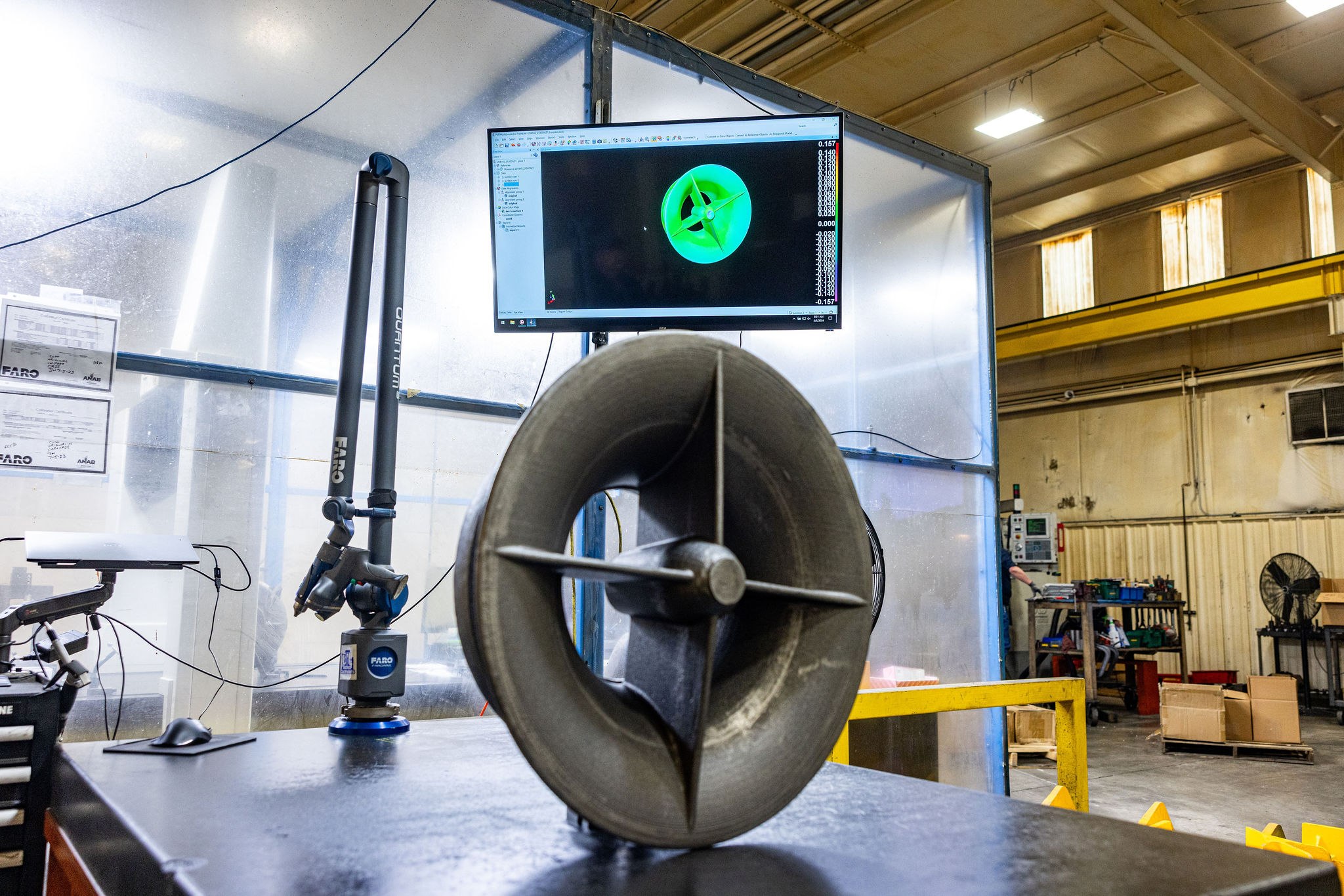
- Scanner accuracy matters as much as mesh density. An articulated laser arm (FARO-class, structured-light) will hit 25–100 µm on a well-prepared cast surface; a low-end handheld scanner may only manage 0.3–0.5 mm. See FARO on 3D scanning efficiency in reverse engineering and Creaform on 3D scanning for reverse engineering and QC of cast parts.
If the scan was done for a marketing render or a visualization, it will almost certainly need to be recaptured on the critical features. That is normal — not every scan is done for a foundry.
Requirement 3 — Recovered wall thickness (the biggest silent gotcha)
A scan captures the part's outer surface. It does not capture wall thickness — which is what a foundry actually pours. If the walls have worn, corroded, or eroded, the scan will silently show the worn wall thickness as the design wall thickness, and the replacement will be cast to the same worn dimension. The failure mode repeats on install. This is the single biggest procurement mistake we see on inbound scan-based RFQs.
Recovery of wall thickness is done one of three ways, and the RFQ should say which is expected:
- Symmetry and unworn reference features on the same part. Most castings have some region that saw little or no service wear — the outer flange faces, the bolt bosses, the areas outside the fluid path. Those regions anchor the as-new wall thickness for the rest of the part by extrusion, offset, or symmetry.
- A less-worn sister part scanned alongside the worn one. If two of the same part came off the same line at different service ages, scan both. The less-worn part sets the as-new dimension; the worn one shows the wear pattern.
- Design intent from OEM literature, drawings, or catalog cuts. Even a decades-old service manual, general-arrangement drawing, or product-line brochure with a nominal wall thickness call-out is enough to anchor the recovery. Send whatever you have.
Wall thickness also drives the solidification behavior, feeding requirements, and hot-spot map in the mold. That is why the walls get simulated in MAGMA / NovaCast before any sand is printed — see our Simulate Before You Pour article for the engineering behind that step.
Requirement 4 — Coverage: internal geometry and hidden features

External surface scans capture what a camera or a laser can see. They do not capture internal geometry — cores, water jackets, oil galleries, port cross-sections, hidden bores — because the beam cannot reach past the wall. On a housing, valve body, manifold, cylinder, or compressor part, the internal geometry is often the whole reason the part exists. The scan file has to represent it explicitly, or the mold cannot be built.
Coverage of internal geometry is captured one of three ways:
- Industrial CT scanning through a bureau — the non-destructive path. A CT bureau images the part slice-by-slice and reconstructs both external and internal geometry into one point cloud. Limited by part size, density, and cost. We help arrange CT through a bureau when the application requires it — plan for the extra week and the CT invoice on top of your line item.
- Destructive sectioning of one sample part. One physical part is cut on the parting line of interest and the cavity is either scanned directly or measured with a CMM. Cheap, fast, definitive. Costs you one sample.
- Measurement of the mating internal. The shaft, bearing, plug, seat, gasket, or valve internal that sits inside the cavity often gives the cavity dimensions by mate. Scan the internal too and let the geometry drop into place.
Whichever method is used, flag internal geometry in the RFQ before the scan happens rather than after. A one-week reset to add CT scanning at the front of the workflow is much cheaper than a poured mold that missed a core.
Requirement 5 — What to send with the scan file
The scan file is only half the RFQ. The other half is the context that turns a shape into a manufacturable part. Send these alongside the mesh:
- The material: known alloy and ASTM grade if you have it, or the service conditions (fluid, temperature, pressure, wear or corrosion mode) so we can call out a candidate grade — gray iron (ASTM A48), ductile iron (ASTM A536), carbon steel (ASTM A216), stainless (ASTM A743) — or an OES coupon from the original part so we can identify the alloy in-house. See metals poured.
- The mating interfaces: what does the part have to mate with on install? Shafts, bearings, gaskets, flanges, bolt-up hardware, seals. Recovered tolerances are anchored to the mate, not to what the worn part measures.
- The critical features: on the mesh, mark which surfaces are functional (bores, bearing seats, sealing faces, flange faces, bolt patterns) and which are non-functional (outer walls, cosmetic surfaces). We machine the functional features to print; the rest come out as-cast.
- Acceptance criteria: required NDE and level (LPI per ASTM E165, MPI per ASTM E709, RT if required), MTR grade (EN 10204 2.2 / 3.1 / 3.2), FAI / PPAP requirements, hydrostatic test if applicable, balance grade for rotating parts (ISO 21940-11).
- Quantity — 1 to a few dozen is typical for reverse-engineered work — and whether repeat orders are likely.
- Any OEM literature: drawings (partial is fine), catalog cuts, service manuals, general-arrangement prints, prior inspection reports. A 40-year-old microfiche is still data.
- The schedule. When is the part needed on a truck? Downtime jobs get flagged and run hot.
Common scan-file mistakes we see on inbound RFQs
Engineer-to-engineer, here are the recurring mistakes that force a second round on an otherwise-good project:
- No units in the file or the file name. The single most common recapture cause. Put "mm" or "in" in the file name.
- The mesh is a screenshot, not a mesh. A PNG or PDF of a scanned model is not a scan file. Send the actual STL / PLY / OBJ.
- Only the external surface, no callout that internal geometry exists. The internal geometry gets discovered on the first drawing review and adds a week to the schedule. Call it out on day one.
- Marketing-quality resolution. A visualization-grade scan is not a manufacturing-grade scan. If the file is under a few tens of MB for a hand-sized part, it is almost certainly under-resolved for foundry use.
- Alloy declared as "steel" or "stainless" with no grade. There are hundreds of cast steel grades and a dozen cast stainless families with very different mechanical, corrosion, and weldability behaviors. See specifying an ASTM grade for a replacement casting for the decision path.
- NDE requested without a level. "LPI required" is not a spec; "LPI per ASTM E165, acceptance level per ASME B16.34 App. III" is a spec. Level determines the pour and the cleaning step, so it belongs on the RFQ.
- Skipping the MTR. Even for one piece, the MTR on the heat is the document the reliability team files for the asset. Request it up front and it costs nothing; request it after the pour and the coupon may already be scrapped.
When NOT to send a scan yet (and what to send instead)
A scan is not always the right input. If any of these apply, send the alternative first and hold the scan:
- You have the original drawing. A released drawing with tolerances and material call-outs is more valuable than a scan. Send the drawing; we will scan the sample only if the mating conditions require a check.
- The OEM is still supplying the part on reasonable terms. Buy the OEM part. Reverse-engineering-from-a-scan is for the case where the OEM is gone, the queue is unworkable, or the part has drifted from the original spec.
- The part is high-volume production. If you are buying thousands per year of a standard part, a permanent pattern or a machined-from-billet path is likely cheaper per piece than patternless. We are short-run specialists; we will tell you when the volume calls for a different supplier.
- You do not have the physical part. Photos, drawings, and OEM literature are still workable — we start there and add a scan only if the recovered geometry needs to be checked against a physical sample.
- Hobby, decorative, unspecified projects. Engineering-grade scan-to-cast with an MTR, LPI, and FAI is real engineering paperwork. If the part has no service condition and no material call-out, this workflow is overbuilt for the job.
Where the scan file goes once we have it
A good scan file with a good RFQ drops straight into the reverse-engineering + patternless-casting workflow: mesh cleanup and CAD reconstruction (see reverse-engineering a worn casting from a sample or 3D scan), solidification simulation in MAGMA / NovaCast, mold generation as a 3D-printed sand mold (or, on repeat-order short runs, one of our four ABB robotic molders), pour in gray iron / ductile iron / steel / stainless / aluminum (metals poured), heat treat as the grade requires, CNC machining to print on the critical features (CNC machining), and NDE / FAI / MTR per the acceptance package (inspection & QC). End-to-end this typically runs 3–5 weeks for a one-off reverse-engineered casting — roughly 1 week on the scan / CAD side, 1 week on simulation and mold print, 1 week on pour and heat treat, and 1–2 weeks on machining, NDE, and final inspection. Downtime jobs are flagged and run hot; call before you ship.
Related reading on this site
- Reverse-engineering a worn casting from a sample or 3D scan — what we do with the file after it arrives.
- From broken part to digital blueprint — the broader patternless recovery workflow.
- 3D scanning & digital twin technical wiki — the scanning + reconstruction method in more depth.
- Specifying an ASTM grade for a replacement casting — the material-callout companion.
- No-minimum steel casting foundry: how short-run pricing works — what the quote structure looks like once the scan file is in.
- Legacy part replication — the full capability page.
- Low-volume, high-complexity castings — the anchor capability page.
Sources & standards
- ISO 8062-3 — Dimensional and geometrical tolerances for moulded parts (castings).
- ISO 2768 — General tolerances for linear and angular dimensions and geometric tolerances.
- EN 10204 — Metallic products: types of inspection documents (2.2 / 3.1 / 3.2 MTR levels).
- ISO 21940-11 — Mechanical vibration: rotor balancing procedures and tolerances.
- ASTM E165 — Standard Practice for Liquid Penetrant Testing.
- ASTM E709 — Standard Guide for Magnetic Particle Testing.
- ASTM A48 — Gray Iron Castings.
- ASTM A536 — Ductile Iron Castings.
- ASTM A216 — Steel Castings, Carbon, Suitable for Fusion Welding, for High-Temperature Service.
- ASTM A743 — Castings, Iron-Chromium, Iron-Chromium-Nickel, Corrosion-Resistant, for General Application.
- ASTM B26 — Aluminum-Alloy Sand Castings.
- FARO — 3D scanning efficiency in reverse engineering.
- Creaform — 3D scanning for reverse engineering and QC of cast parts.
- Artec 3D — reverse-engineering learning center.
- ATT Inc. — Professional 3D scanning reverse engineering services.
- Steel Founders' Society of America (SFSA) — industry reference for steel casting practice.
FAQ
What file formats do you accept for a 3D scan of a part you want cast?
For a scan we prefer a watertight mesh in STL, PLY, or OBJ format, exported in millimeters or inches (state which), with a stated coordinate system and up-direction. If your workflow has already turned the scan into a parametric CAD solid, we prefer STEP (AP203 or AP214) or IGES, and we can also open native SolidWorks, Inventor, Creo, and Fusion 360 files. What we cannot use directly is a raw point cloud (PTX / E57 / XYZ) — we can convert it, but that is a paid engineering step and it costs time. If a mesh is all you have, ship the mesh; if a solid is all you have, ship the solid; if you have both, ship both.
How dense a mesh does the scan need to be?
Dense enough that the features that matter — bores, sealing faces, bolt patterns, vane profiles, wear surfaces — are resolved with a triangle edge length small compared to the feature's tolerance. As a rule of thumb, aim for a mesh where triangle edges on critical features are at or below one-third of the feature's tolerance band. For a typical industrial cast part in the size class we work in, that lands in the 0.1–0.3 mm range on critical features and 0.5–1.0 mm on the general envelope. A scan that meets that resolution is enough to build a manufacturable CAD model; a scan that is coarser than that will need re-scanning of the critical zones before we can quote a real number.
Can you cast a part from a scan alone if the walls are worn or corroded?
Sometimes — but the scan alone is rarely enough on a worn part. A scan captures the part as it is today, not as it was designed. To rebuild the as-new geometry we need unworn reference features on the same part (symmetry planes, mating faces, bolt patterns, adjacent unworn surfaces) or a less-worn sister part alongside the worn one. If the entire part is uniformly worn or eroded past the original surfaces, the scan tells us the failure mode but not the as-new dimension — in that case we need photos, catalog cuts, drawings of the mating assembly, or a sister part to anchor the rebuild.
What if the part has internal geometry we cannot see from outside — cores, water jackets, hidden passages?
External surface scans miss internal geometry by definition. The three paths, in order: (1) industrial CT scanning through a bureau — the only fully non-destructive way to capture internal cavities on a finished part, limited by part size and density; we help arrange it; (2) destructive sectioning of one sample to capture the cavity profile directly — cheap, fast, definitive, and it costs you one part; (3) measurement from the mating internal — the shaft, plug, valve internal, or gasket that sits in the cavity — when the internal has a physical mate. Flag internal geometry up front in the RFQ so the correct capture method is quoted before the scan happens rather than after.
Do we need to identify the alloy before you can quote?
For a real quote, yes — or at least tell us the service (fluid, temperature, pressure, wear or corrosion mode) so we can call out a candidate grade. If the alloy of the original is unknown, ship us a small button or coupon from the original part and we run optical-emission spectrometry (OES) in-house to identify it. Handheld XRF is useful as field triage but does not resolve carbon content and only reads the surface, so we do not price a real casting on XRF alone. Whatever you send, we pour the replacement to a named ASTM grade with a Material Test Report (MTR) on the heat so the chemistry and mechanicals are on the paperwork.
The scan was done by a third-party service — is that okay, or do you need to redo it?
A third-party scan is fine if it meets the format, resolution, and coverage requirements above. Send the raw mesh (not just a screenshot or a PDF report) and, if the scanner produced them, the deviation report and any alignment/datum reference points. If the third-party scan is a marketing-quality visualization rather than an engineering-grade capture — coarse mesh, no scale, no coordinate system, no coverage of internal features — we will let you know and quote what needs to be recaptured. Most engineering-grade scans from FARO, Creaform, Artec, Hexagon, ZEISS, and similar equipment come across cleanly.